Watermain Leaks – A Costly Contributor to Energy Consumption, NRW Loss
Date:
Publication:
Calculating watermain leakage can justify the need for continual monitoring
Ongoing watermain leaks can waste a lot of energy, resources and money, especially on flat terrain where municipal pumping is required to keep the system pressurized and where water is purchased from a local municipal purveyor at retail rates.
Mueller was recently hired by an energy performance firm to survey a federal government water distribution network in Ontario to determine if leakage was contributing to unnecessary energy consumption.
Approximately 46 km (28.5 miles) of watermains were surveyed using EchoWave acoustic leak detection to non-invasively detect and pinpoint leaks. Echologics field technicians set up 222 access points on pipes, valves, and hydrants to attach LeakFinder-ST leak correlator sensors. The sensors listen for noise created by a leak. If a leak is detected, the technology uses the distance and time delay between sensors to accurately determine the position of the leak.
The leak detection survey was conducted on pipes across the network, consisting of various materials, most of which were cast iron and polyvinyl chloride (PVC), ranging from 150 to 400 mm (6 to 16 in.) in diameter. For metallic mains, the sensors were attached magnetically to valves. For PVC pipes, technicians used hydrophone sensors mounted to the side port of fully charged fire hydrants for elevated acoustic sensitivity.
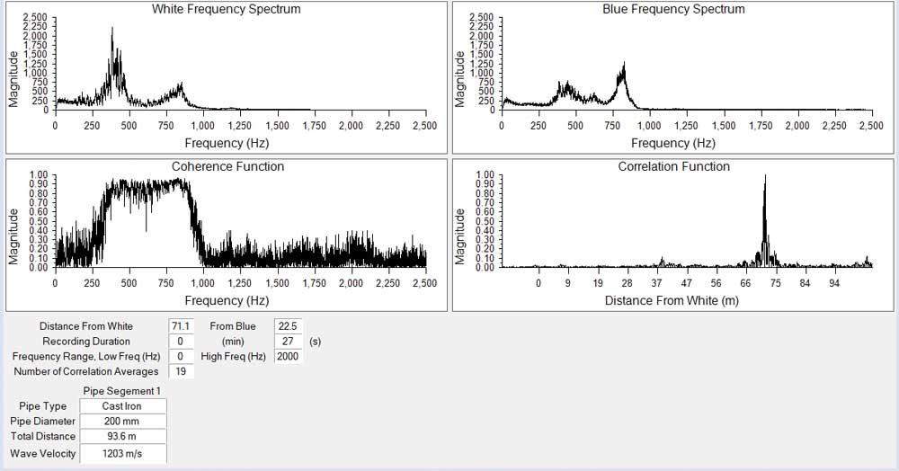
The sensors were connected by cable to a transmitter which communicated with a receiver at the technician’s computer. The acoustic data was processed on-site to determine if there was evidence of a leak. Several criteria must be met for audio recordings to provide a positive leak detection result. This includes but is not limited to, a clean, distinctive correlation peak, an observable coherence level, a similar frequency spectrum in each channel, and/or a minimum amount of clipping in the time signal. The water main leak had all these indications.
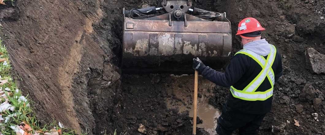
A total of seven leaks (including hydrant, service piping and watermain leaks) were identified, and one of the leaks on an 8-in. watermain was significantly large. Given that the size of this watermain leak was identified to be large, the Echologics team was on site during the leak excavation and repair activities. This leak detection team was able to confirm the leak position between two fire hydrants as being approximately 23 m from the second hydrant, reconfirming the original position reported.
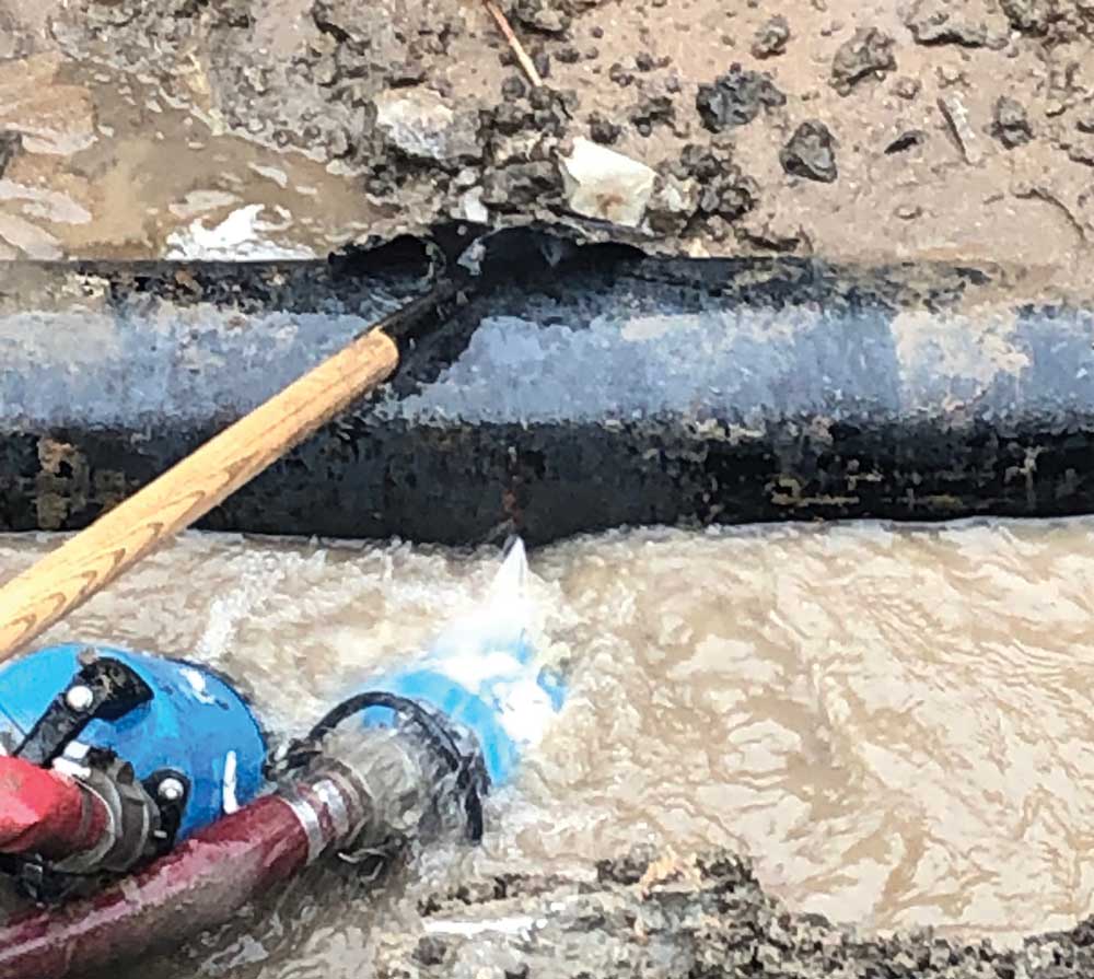
Upon excavation, it was determined that the circumferential crack on the 200-mm (8-in.) cast iron watermain had an average width of approximately 3 mm (1/8-in.) and covered over 50 per cent of the circumference of the pipeline. The crack was determined through visual observations as actually being slightly less than 3 mm (1/8-in.) wide at the edges but approximately 6 mm (1/4-in.) wide at the bottom of the pipe. The average 3-mm (1/8-in.) wide crack was believed to be a conservative average estimate for the entire crack length.
The leak was repaired utilizing a stainless-steel repair clamp, which is a standard repair for this type of leak. The watermain did not show signs of severe or widespread corrosion. The following day, Echologics crews returned to the site to complete a post-leak repair investigation to confirm that no additional leaks were present, and the correlator confirmed that the repair was successful.
Watermain Leak Size Estimation
The initial leak size estimate at time of survey for the water main leak was between 297 and 731 LPM (78 – 193 GPM). This range is typical for non-surfacing water main leaks. With additional information on the type of leak (circumferential crack) and the size of the opening, Echologics was able to make a more accurate assessment of the leak size using the AWWA M36 manual on water audits and loss control programs, along with operator judgment and adjusting for operating pressure.
Two approaches were utilized; one was to convert the leak opening area to an equivalent size of a circular hole and to utilize the orifice equation to determine the leak flow rate, and the second method was to utilize published literature on average flow rate from cracks to estimate the leak size.
Method 1 – Equivalent Hole Method
The circumferential crack had a width of approximately 3 mm, covering at least 50 per cent of the circumference of the pipeline.
The area of the opening of the leak can be calculated as:
AreaLeak = Width x Length = 3 mm x (0.5 x PI x 200 mm) = 942 mm² or 0.000942 m²
The Orifice Equation to calculate leak flowrate is defined as:
FlowLeak = AreaLeak x Cd x (2 x g x Pressure)0.5
For rough edges such as with this crack, a Cd of 0.45 is recommended and is assumed to be conservative. For perfectly circular holes, a Cd of 0.62 is recommended. The pressure at the site was recorded as being 74 psi or 52 m of head.
FlowLeak = 0.000942 x 0.45 x (2 x 9.81 x 52)0.5 = 0.0135 m3/s or 813 LPM.
Method 2 – Flow Through a Crack
AWWA M36 manual on water audits and loss control programs provides industry best practices associated with leak detection and leak repair savings estimations. On page 251 of this manual, Table 7-5 provides estimated flow rates from cracks in pipelines. Based on this table, the following estimate can be calculated:
FlowLeak = 12” crack x 23 GPM per 1” of crack at 74 psi = 276 USGPM or 1,043 LPM
Table 7-5 utilizes a coefficient of discharge of 0.6 which, would be at the upper limit of the leak flowrate calculation. Using both methods it was estimated that the actual leak flowrate was between 750 and 1,000 LPM (198 – 264 GPM).
The cost of a leak this size is close to $1 million a year, which is a large enough number to justify a regular leak monitoring program. Large leaks can consume a significant amount of energy by continuously pumping water to maintain desirable water pressure. This also puts unnecessary wear on pumping equipment that is used to keep water flowing that never makes it to the tap.
The other six leaks are also being repaired. The absence of leaks within the remaining watermains is not necessarily indicative of good pipe wall condition. Therefore, recommendations were put forward to assess the condition of the remaining water pipes, considering the consequence of failure and other potential issues such as low pressure or poor water quality complaints. In addition, a regularly scheduled leak detection survey was recommended as a relatively inexpensive option for finding leaks within the system.
As watermains are often buried deeper in Canada than in many other parts of North America, leaks are less likely to surface and can go undetected for several years. As the main artery of the water distribution system, watermains transport huge volumes of water and are often under higher pressure to meet demand over long distances.
Consequently, when a leak does occur, the volume of water loss is often greater than on smaller pipes. The best solution for watermains is a permanent leak monitoring system that can find most leaks on a pipeline, including small leaks, before they turn into catastrophic failures.
Click here to read the article in Trenchless Technology Magazine